
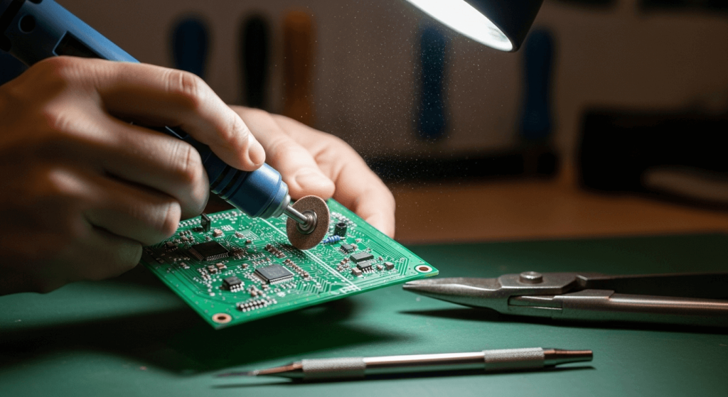
Cutting a printed circuit board (PCB) is a core skill for electronics hobbyists, repair technicians, and prototyping engineers. Whether you’re modifying a pre-assembled board to fit a custom enclosure, trimming a panel of identical boards for a batch project, or repairing a damaged edge on a critical circuit, precise cuts prevent costly damage to copper traces, component solder joints, and the fiberglass substrate itself. Unlike cutting wood or plastic, PCB material is brittle and prone to splintering if handled incorrectly, so following a structured, safety-first process is non-negotiable for clean, functional results. This guide walks you through every step, from tool selection to post-cut testing, to help you get precise, repeatable results every time. If you’re new to electronics prototyping, our step-by-step DIY project guides cover everything from basic component soldering to custom enclosure builds.
What You’ll Need Before Starting
Gathering the right tools and safety gear before you begin cuts down on errors and reduces risk of injury. Use the checklist below to ensure you’re fully prepared:
Safety Gear
- Safety goggles with side shields: Protect your eyes from flying fiberglass shards and dust.
- N95 respirator: Cutting FR4 (the standard fiberglass PCB material) releases respirable glass particles that can cause long-term lung irritation if inhaled. The Occupational Safety and Health Administration (OSHA) recommends N95 respirators for all tasks that generate respirable dust, including PCB cutting, to prevent long-term respiratory irritation OSHA workshop safety guidelines.
- Nitrile gloves: Prevent sharp fiberglass splinters from cutting your skin during handling and sanding.
Marking and Measuring Tools
- Ruler or digital caliper: For measuring cut lines to within 0.5mm accuracy, critical for avoiding severed traces.
- Fine-tip permanent marker or PCB scribe: Pencil smudges easily on the resin surface of PCBs, so a permanent marker ensures your cut line stays visible throughout the process.
Cutting Tools
Choose a tool matched to your board thickness and cut type (see the comparison table later in this guide for full details):
- PCB shear or aviation snips: Best for straight cuts on standard 1.6mm thick FR4 boards.
- Rotary tool with carbide cutting wheel: Ideal for curved cuts, intricate shapes, or small prototype boards.
- Mini table saw or bandsaw: Best for long, straight cuts on thick (2mm+) or multi-layer boards.
- Carbide-tipped utility knife: A low-cost option for scoring and breaking thin, single-layer boards.
Support and Finishing Tools
- Non-slip work mat: Prevents the board from shifting during cutting.
- PCB vise or clamps: Secures the board firmly without crushing mounted components.
- Fine-grit sandpaper (220+ grit) or deburring tool: Smooths rough edges and removes sharp fiberglass splinters after cutting. Keeping small hand tools like rotary tools and utility knives within easy reach using simple tool organization tips reduces workflow interruptions and keeps your work area safe.
Pre-Cut Preparation for Error-Free Results
Skipping pre-cut planning is the most common cause of damaged PCBs and wasted materials. Follow these steps to set yourself up for success:
Verify Board Specifications
First, confirm your PCB’s thickness and material. Standard hobbyist FR4 boards are 1.6mm thick, but high-power or multi-layer boards can be 2mm or thicker, which requires a more robust cutting tool. The IPC (Association Connecting Electronics Industries), a leading global trade association for the electronics manufacturing industry, sets voluntary standards for safe PCB handling to minimize exposure to fiberglass dust and chemical irritants IPC industry standards for PCB handling. If your board has pre-mounted components, note their height and position to avoid clamping directly over them, which can crush SMD parts or loosen through-hole solder joints.
Mark Your Cut Line Accurately
Measure your cut line twice with a caliper or ruler before marking, and double-check that the line aligns with your project’s requirements (e.g., fitting a specific enclosure cavity). For straight cuts, use a ruler to draw a crisp, continuous line; for curved cuts, use a compass or pre-cut stencil to ensure consistency. Mark the line on the copper side of the board if you’re cutting along the edge of a trace, so you can clearly see your alignment as you cut. If you’re cutting multiple identical boards from a single panel, advanced PCB panelization techniques can reduce material waste and improve consistency.
Step-by-Step Cutting Process
Follow these steps in order for clean, precise cuts every time:
Secure the PCB to Your Work Surface
Clamp the board firmly to a non-slip work mat, positioning the cut line so it extends 1-2mm over the edge of your workbench if you’re using a saw to avoid damaging your table surface. If using a rotary tool, a PCB vise holds the board at a comfortable working angle and eliminates movement entirely. Avoid over-tightening clamps, as this can crack thin PCBs or damage mounted components.
Execute the Cut
Adjust your approach based on your chosen tool:
- Scoring with a utility knife: Score the board 5-10 times along the marked line with firm, even pressure, then place the score line over the edge of your workbench and apply gentle downward pressure to snap the board cleanly. Do not try to cut all the way through in one pass, as this causes chipping and splintering.
- Using a shear or snips: Align the tool jaws exactly with your marked line, then squeeze firmly in one smooth, steady motion. Wiggling the tool during the cut will create ragged, uneven edges.
- Using a rotary tool or saw: Start with a slow, low-power pass to create a shallow groove along your cut line, then increase speed slightly to cut through the full thickness of the board. Never force the tool, as this will break cutting wheels or splinter the fiberglass.
Smooth and Refine the Edges
After cutting, the board edge will have rough burrs and sharp fiberglass splinters. Start with 120-grit sandpaper to remove large imperfections, then switch to 320+ grit sandpaper for a smooth finish. If you plan to solder components to the cut edge, use a deburring tool to remove all sharp fragments, which can cause electrical shorts if they get trapped between copper traces. Wipe the board with a lint-free cloth and isopropyl alcohol after sanding to remove dust that could interfere with soldering later.
 Follow marked cut lines carefully to avoid damaging adjacent copper traces.
Tool Comparison for Different Use Cases
Use this table to select the best tool for your specific project needs:
| Tool Type | Best Use Case | Pros | Cons |
|---|---|---|---|
| PCB Shear / Aviation Snips | Straight cuts on 1.6mm standard FR4 boards | No splintering, fast, low effort | Not suitable for curved cuts or boards thicker than 2mm |
| Rotary Tool (with carbide cutting wheel) | Curved cuts, intricate shapes, small boards | Highly versatile, precise for detailed work | Slower for long straight cuts, cutting wheels wear down after 10-15 cuts on standard FR4 |
| Mini Table Saw | Long straight cuts on thick or multi-layer boards | Consistent, fast for batch cuts | Higher upfront cost, requires dedicated workspace |
| Carbide-Tipped Utility Knife | Low-cost scoring for thin, single-layer boards | Inexpensive, no power required | Requires multiple passes, higher risk of chipping if rushed |
The right cutting tool for your PCB depends on its thickness and material, much like selecting the right blade for cutting thick foam insulation.
Common Mistakes to Avoid
Even experienced electronics hobbyists run into these avoidable errors:
- Rushing the cut: Forcing the tool or cutting too fast causes splintering, broken cutting wheels, and severed copper traces. In practice, a slow, steady pass produces a cleaner result 90% of the time, even if it takes a few extra seconds.
- Using a dull cutting tool: Dull utility knives or worn rotary wheels crush the fiberglass substrate instead of cutting it, leading to ragged edges and increased risk of trace damage. Replace cutting wheels after 10-15 cuts on standard FR4 to maintain performance.
- Skipping dust protection: Many hobbyists skip the N95 mask for small cuts, but even brief exposure to fiberglass dust can cause skin and lung irritation. Always wear full safety gear, even for 1-minute cuts.
- Cutting without securing the board: A shifting board leads to uneven cuts, broken traces, and even injury if the tool slips. Always clamp or vise the board firmly before starting any cut.
- Overlooking component placement: If your PCB has mounted through-hole components, leave at least 5mm of space between your cut line and any component leads to avoid knocking parts loose or damaging solder joints.
- Ignoring tool storage best practices: Storing larger power tools like mini table saws out of foot traffic paths, following safe tool storage practices, prevents tripping hazards and accidental damage to your equipment.
 Account for mounted components when marking your cut line to avoid knocking parts loose or severing critical traces.
Credit: www.wellpcb.com
Account for mounted components when marking your cut line to avoid knocking parts loose or severing critical traces.
Credit: www.wellpcb.com
Post-Cut Testing and Finishing
A precise cut is only half the battle—proper post-cut work ensures your board is functional for your project: First, inspect the cut edge under a magnifying glass to check for nicked or severed copper traces. If you plan to use the board for an active circuit, use a multimeter in continuity mode to test for shorts between adjacent traces, which can be caused by stray fiberglass dust or burrs. If you’re soldering components to the cut edge, tin the exposed copper with a small amount of solder first to prevent oxidation before assembly. If your PCB is mounted in a custom wooden enclosure, oiling wooden cutting boards and other wood components regularly prevents warping and extends their lifespan.
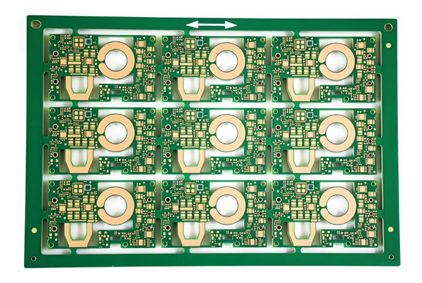 Panelization lets you cut dozens of identical PCBs from a single sheet, reducing material waste for batch hobbyist or production projects.
Credit: topfastpcba.com
Panelization lets you cut dozens of identical PCBs from a single sheet, reducing material waste for batch hobbyist or production projects.
Credit: topfastpcba.com
Frequently Asked Questions
What is the best tool for cutting a PCB at home?
For most hobbyist projects, a carbide-tipped utility knife or PCB shear is the best choice for straight cuts on standard 1.6mm FR4 boards. For curved or intricate cuts, a rotary tool with a carbide cutting wheel offers the most precision. For batch cuts of multiple identical boards, a mini table saw provides consistent, fast results.
Can I cut a PCB without damaging the copper traces?
Yes, as long as you cut slowly along a clearly marked line that runs parallel to or between traces, rather than across them. Avoid forcing your cutting tool, as excessive pressure can delaminate the copper layer from the fiberglass substrate.
Do I need to wear a mask when cutting PCBs?
Absolutely. Cutting fiberglass PCBs releases fine glass particles that can irritate your lungs and skin. Wear a N95 respirator, safety goggles, and nitrile gloves for all cutting tasks, even for small, quick cuts.
Can I cut a PCB that has already been assembled with components?
Yes, but you will need to adjust your cut line to avoid mounted components. Leave at least 5mm of space between your cut line and any component leads or solder joints to prevent damaging parts or causing electrical shorts.
Conclusion
Cutting a PCB circuit board doesn’t have to be intimidating, as long as you prioritize preparation, use the right tools for your specific board, and follow safety guidelines consistently. Precise cuts protect your components, reduce material waste, and ensure your final circuit functions as intended. For more advanced methods like panelization and batch cutting, check out our advanced PCB panelization techniques guide. With practice, you’ll be able to make clean, accurate cuts for any project, from one-off hobbyist builds to small production runs.

I’m Abby Lu, a passionate home cook who loves simplifying everyday meals. At PlugChef.com, I share product reviews and cooking guides to help you find the best tools for your kitchen.
Related posts:
 Eco-Friendly Kitchen Ideas to Reduce Waste and Save Energy
 How to Get Rid of Oils from Kitchen Counter Organically: Eco-Friendly Tips
 How to Grow Organic Kitchen Garden: Expert Tips
 Best Eco-Friendly Kitchen Cookware for Healthy Cooking
 How Do You Make a Butcher Block Cutting Board: Easy DIY Guide
 Top 10 Best Non-Toxic Cooking Utensils – Safe & Durable Choices for Healthy Homes

